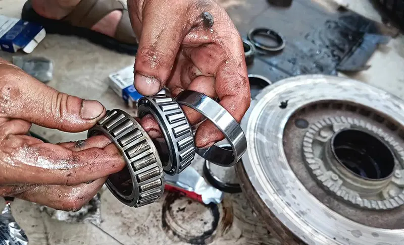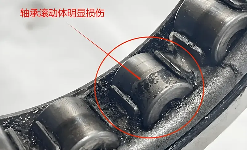
Once deep groove ball bearings have been installed in the host machine, there is a measurement parameter known as ‘cyclic rotational accuracy’. Variations in this parameter occur in an approximately repetitive pattern, and the number of revolutions required for this repetition can be used to characterise the ‘quasi-period’ of the cyclic rotational accuracy. If the amplitude variation within the quasi-period is significant, this indicates poor cyclic rotational accuracy. By applying an appropriate preload to the deep groove ball bearing spindle, the rotational speed can be gradually increased to a level close to the operating speed. This achieves the ‘running-in’ of the bearing, thereby improving the spindle’s cyclic rotational accuracy.
There is currently a design scheme for precision instruments that can enhance the accuracy of deep-groove ball bearings: when a 6202/P2 bearing is used on the spindle but the accuracy still fails to meet requirements, the journal can be enlarged and a raceway machined onto it to replace the bearing inner ring; simultaneously, the steel balls are precisely measured, and each set of balls is distributed in a pattern of ‘three large and three small balls, spaced at approximately 120°’. As this design reduces the number of machined surfaces—and consequently the number of mating surfaces—the rigidity of the shaft-bearing system is improved; furthermore, the close, equidistant distribution of three large and three small steel balls enhances the rotational precision of the shaft, ultimately meeting the instrument’s accuracy requirements.
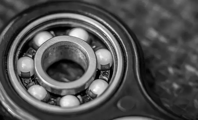
Step one: Measure the dimensions of the shaft and the bearing housing bore to determine the bearing’s fit accuracy. In this arrangement, the inner ring of the bearing has an interference fit with the shaft, whilst the outer ring has a clearance fit with the bearing housing bore.
Step 2: Fit the front bearing (fixed end) onto the shaft: thoroughly clean the bearing with clean kerosene, then use a grease gun to inject a measured quantity of grease into the bearing; heat the bearing to 20–30 °C, and use a hydraulic press to press-fit the bearing onto the shaft end; Press-fit the locking sleeve onto the shaft and apply appropriate pressure to the bearing end face to achieve axial positioning of the bearing; wrap the strap of a spring balance around the outer ring of the bearing and, by measuring the starting torque, check whether there is any significant change in the specified preload.
Step 3: Install the deep-groove ball bearing–shaft assembly into the housing bore: Heat the housing bore to 20–30 °C, then install the bearing–shaft assembly into the bore using continuous and gentle pressure; Adjust the front cover; using the outer end face of the bearing housing as a reference, place the dial gauge’s tip against the surface of the journal and rotate the shaft to measure its runout; secure the dial gauge to the shaft so that the tip contacts the inner surface of the rear housing bore, then rotate the shaft to measure the coaxiality between the front and rear housing bores.
Step 4: Install the free-end bearing selectively at a position where it can offset deviations (i.e. at the rear support of the bearing housing), to minimise roundness and coaxiality deviations between the various components as much as possible.
To measure the actual fitting accuracy of deep-groove ball bearings during installation, specialised measurement methods and tools must be employed to carry out precise measurements of the mating surfaces of the bearing’s inner bore and outer diameter. All measurement parameters relating to the inner and outer diameters must be fully recorded, and the measured data must be comprehensively analysed. Based on this, the dimensions of the bearing mounting areas on the shaft and housing bore must be precisely matched.
When measuring the corresponding dimensions and geometric shapes of the machined shaft and housing bore, it is essential to ensure that the ambient temperature during measurement is consistent with that at the time the bearing was measured. To ensure a good actual fit, the surface roughness of the bearing contact surfaces on both the shaft and the housing bore should be as low as possible. During the measurement process, two sets of markings indicating the ‘direction of maximum deviation’ must be applied to the outer circumference and inner bore of the bearing, as well as to the corresponding surfaces of the shaft and housing bore (on both sides adjacent to the assembly chamfers). This ensures that, during actual assembly, the maximum deviations of the mating surfaces are aligned in the same direction, thereby partially cancelling out the deviations between the two surfaces after assembly. Taking deviation compensation into account comprehensively not only improves the rotational accuracy of each end bearing but also partially eliminates the coaxiality error between the housing bores of the two bearings and the journal ends.